![]()
Congratulations. You have just discovered the finest IRS bushing kit available on the market today.
If you are changing your car from completely stock to this set-up, you will be astounded with the difference.
We guarantee it!
Installation Photo's and Tips.
 |
 |
| Here is the proper tool to remove the toe link. |
A screw driver or a pry bar and a little force pops the halfshaft right out of the differential. |
Upper Control Arm Bushing Removal.
 |
 |
 |
| First is the saw cut of the upper control arm bushing flange for the removal tool to fit. |
Saw cut the upper control arm bushing flange at 1.750". |
Here is how the tool sits on the upper control arm to remove the bushing once the flange is cut. |
 |
 |
| Before reinstalling the upper control arm into the IRS, clean and smooth out the inside of the buckets with a disk sander. |
Then spread the ears of the bucket slightly and get them as parallel to each other as possible. |
Lower Control Arm Bushing Removal.
 |
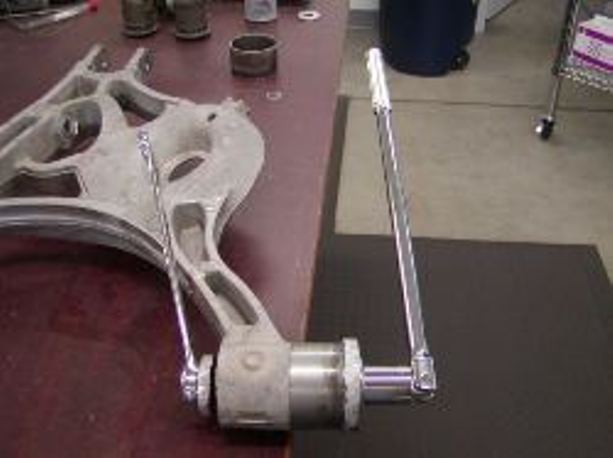 |
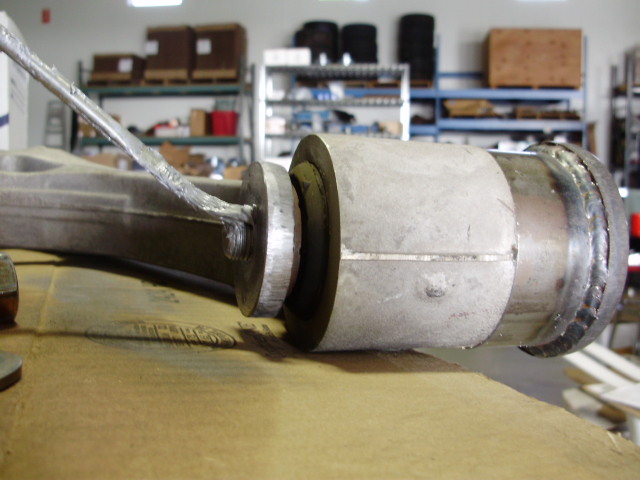
| Here is a picture of the removal tool removing the larger rear bushing. Lubricate threads well with never-seize. The large washer is what pulls the bushing out of the control arm. |
This
does take considerable effort. Get a long 1/2" or even 3/4" breaker bar and wail on this thing. You can skip going to the gym the night you do this! |
 |
 |
| The later model cobra's have a washer tack welded on the forward portion of the rear LCA bucket. |
I like to use an air
chisel and they pop right off. |
 |
 |
| Photo of the washer removed. | Once the washer is
removed you need to grind it smooth. |
 |
 |
| Lower Control Arm bolt misalignment. |
Lower Control Arm bolt alignment corrected. |
| The
bushed control arm with the inner sleeves installed, should be dry fit into the subframe with the LCA bolts. If misalignment is encountered the misaligned hole will need to be relieved with a rat tail file, Dremel tool or a rotary burr until the bolt slips through without resistance. |
|
|
Subframe Bushing Removal. Warning!!! Removal of the subframe bushings can be difficult. The most painless approach would be to heat the outer metal surrounding the subframe bushing with a torch. Heat this to 350-400 degrees. You can check the temperature with an infrared thermometer if you have one. This will break the vulcanizing and the bushing should slide right out with the FT 2100 OEM bushing removal tool set. |
| Click here to check out our informational videos: http://www.fulltiltboogieracing.com/informational_videos.htm |
| If you don't have a torch you will encounter a lot of resistance removing the bushings. If you don't take the heating approach stated above take a 1/4" drill bit and drill numerous holes to weaken the subframe bushings. It is preferable to drill as close to the outer metal sleeve as you can. Drill at least 10 holes on each end of the bushing. The rubber is vulcanized in this sleeve and this will free it up for easier removal. If you put excess pressure on the threaded rod you’re going to break it. If you have a ball joint removal tool, these will also work. |
 |
 |
 |
| Here is
a photo of the subframe bushing removal tool on the subframe. |
The subframe bushings are VERY difficult to remove and drilling them helps ALOT! Here is a pic of the bushing drilled with a 1/4" drill. Keep the holes as close to the metal sleeve as possible and be sure to drill from both sides. |
Here is the bushing almost out. Put double large washers on the bushing side. If you get a stubborn bushing, apply a little heat to it, that will help the vulcanized rubber separate from the inner metal sleeve. |
 |
 |
 |
| Subframe with removal tools. | Drilled subframe bushing after removal. |
Drilled then removed subframe bushings. |
Please take note: The outer metal sleeve on the subframe bushing location stays!
 |
 |
| Here is a 2" diameter
coarse wire wheel cleaning the bores in preparation for the installation of the UHMW subframe bushings. When the wire wheel is brand new, it's a little tough to get it started. It helps starting it on the side with the flange. |
This is what a super clean bore looks like after the wire brushing procedure. |
Rear Differential Support
 |
 |
| The subframe bushing removal tool is also used to remove the factory rear differential mount rubber bushing. |
Rear differential bushing removed. |
 |
 |
 |
| Pressing in the first Delrin bushing. |
First Delrin bushing seated in place. |
Pressing in the second Delrin bushing. |
 |
 |
| This photo is showing the beveled lead on the aluminum sleeve that needs to be pressed in with this leading edge first. |
Here is the inner sleeve being pressed in. |
 |
 |
| Here is the completed assembly. |
Because the Delrin rear diff mount will rub slightly on the rear diff cover, a nice chamfer to the Delrin on a belt sander will give you plenty of clearance. |
 |
 |
| This photo shows where to grind for clearance. |
This photo shows how
close the bracket is to the Ford Racing Diff cover. |
|
For those of you installing our FT 1300 Delrin rear diff support bushing set included in our FT 5000 bushing package, you'll want to check your OEM diff bracket for clearance on the new Ford Racing rear diff cover if that is what you're using. In some instances, the bracket actually makes contact with the New Ford cover and you're going to want to grind or belt sand the bracket for a minimum of 1/8" clearance. |
|
|
Grease Fitting Kit Here are some pictures of the grease fitting kits and installation on the control arms. Grease fittings will assure you a lifetime of trouble free and silent operation. It is highly recommended to install grease fittings. |
 |
|
Drilling the upper control arm. It's nice if you have access to a drill press, but if you don't, you can drill this very carefully by freehand. Drill slowly and use cutting oil. Because of the relatively thin cross section of the UCA at this point we only recommend drilling and tapping for 6mm threads. Anything larger than that is not acceptable or recommended. |
 |
|
Here is the installation of the new tapped 6mm 90 degree grease fittings. The forward eye needs to point down and to the front of the car at about a 10 or 15 degree angle. The rear fitting needs to also point forward but at about a 45 degree angle. I've found these positions to be very favorable. Look at your IRS in the car before you pull it out to see if you agree with the positions of these fittings. That is why the instructions state: Look at your IRS assembly while it is still in the car and pick a good accessible location and what type of angle/orientation you’re going to want for the grease fittings. |
 |
|
IRS LCA Front eye w/90 degree fitting installed on top of the control arm pointing at a 45 degree angle rearward. |
 |
| IRS LCA Rear eye w/straight fitting on the bottom pointing straight down. |
| Here is a short video showing the shimming washer and grease fitting locations. |
 |
 |
 |
| Top view of the IRS with the bushing kit installed. |
Side view. | Rear view. |
 |
| Before putting the subframe assembly back in the chassis, it's a good idea to spread the front mount locations a little bit. They have a tendency to squeeze together making the replacement of the subframe more difficult than it should be. Take the 1/2" threaded rod from your bushing removal tool set along with the largest thick washers and spread this area open a bit. Then, take a UHMW subframe bushing from the subframe kit and try it in the opening to check for clearance, before you install the UHMW bushings into the subframe. |
 |
|
Here is a photo of the front diff support as it should be installed in the vehicle. For all IRS applications regardless of the rear diff mount FT 1300 or FT 1401, you want to raise the front nose of differential up as high as you can without it actually rubbing or touching anywhere on the subframe. The small bushings go on top; usually with a single shimming washer. If you grind the subframe slightly for some additional clearance, you will not need the single shimming washer on top. The large bushings and the remainder of the shimming washers should be placed on the bottom. Put in as many shimming washers as you can on the bottom of each side. Some vehicles may only accept 3 or 4 shimming washers on the bottom, some will take 4 or 5. |
|
Click here for information on setting pinion angle. |
 |
| Adjustable Sway Bar End Links. |
 |
| Here is a photo of the link mounted on a mock-up IRS assembly along with a short video: |
|
The upper and lower mounting bolts will come to you assembled and tight on the heim joints. You will notice there is a thin jamb nut on one of the mounting bolts and a thicker standard thickness nut on the other. The standard thickness nut that goes on the upper mounting point assists in getting the alignment between the anti-sway bar and the control arm improved. This upper mounting bolt is 5mm shorter than the lower mounting bolt. You want to make sure the eyes of the heim joints are lined up when tightening them making sure one is not cocked to one side or the other. Install the link on the outside of the anti-sway bar and from the outside on the lower control arm. |
| When installing these links make sure the car is level and there is no pressure on the links when tightening the mounting hardware. The car will need to be on a drive-on lift or jacked up onto four drive on ramps to do this. |
|
If there is pressure on the links you risk shifting the car's weight from one side to the other. The torque specs for these 10mm nuts are 33 ft. lbs. or 45Nm. |
IRS Torque Specs and Bolt sizes.
(SN-95 IRS Hardware can be found by clicking here)
| Location | Bolt Size |
Head Size |
Torque |
| Rear Subframe-to-rear bracket bolts | 12 x 1.75 x 110mm | 18mm | 76 ft-lbs |
| Subframe rear bracket-to-body bolts | 12 x 1.75 x 35mm | 15mm | 59 ft-lbs |
| Front Subframe-to-body bolts 12mm bolts | 12 x 1.75 x 110mm | 18mm | 76 ft-lbs |
| Front Subframe-to-body bolts for replacement Grade 8, 9/16" bolts | 9/16" x 4 1/2" | 13/16" | 145 ft-lbs |
| Front Subframe-to-body bolts for Ford 14mm replacement bolts | 14 x 2 x 110mm | 18mm | 131 ft-lbs |
|
NOTE: OEM front 12mm subframe bolts need to be upgraded to 9/16" Grade 8 bolts with Grade 8 nyloc locking nuts. Rear subframe bolts need an unthreaded lead on them to guide the floating nut onto the thread to prevent cross-threading. |
|||
| Driveshaft-to-pinion flange (Blue Loctite) | 12 x 1.75 x 25mm | 12 point 12mm |
83 ft-lbs |
| Halfshaft nuts (to rear hub) | 24 x 2 | 36mm | 240-250 ft-lbs |
| Lower control arm and bushing-to-subframe bolts | 16 x 2 x 120mm | 21mm | 184 ft-lbs |
| Lower control arm-to-knuckle | 12 x 1.75 x 90mm | 85 ft-lbs | |
| Upper control arm and bushing-to-subframe | 12 x 1.75 x 70mm | 15mm | 66 ft-lbs |
| Upper control arm bushing-to-knuckle nut | 66 ft-lbs | ||
| Rear diff mount to diff housing bolts | 12 x 1.75 x 60mm | 15mm | 76 ft-lbs |
| Caliper bracket bolts | 12 x 1.75 x 35mm | 15mm | 76 ft-lbs |
| Rear caliper to caliper bracket bolts | 8 x 1.0 x 22mm | 12mm | 25 ft-lbs |
| Brake line to rear brake caliper bolt (Banjo bolt) | 10mm | 30 ft-lbs | |
| Front diff housing to subframe | 12 x 1.75 x 95mm | 15mm | 59 ft-lbs |
| Rear diff support to subframe | 12 x 1.75 x 85mm | 18mm | 85 ft-lbs |
| Shock to lower arm and bushing bolt | 14 x 2 x 120mm | 21mm | 98 ft-lbs |
| Toe link-to-subframe | 10 x 1.5 x 80mm | 13mm | 35 ft-lbs |
| Toe link-to-knuckle castle nut | 12mm x 1.25mm | 18mm | 35 ft-lbs |
| Wheel lug nuts | 1/2" - 20 | 21mm | 95 ft-lbs |
| Sway bar mount to subframe | 10 x 1.5 x 25mm | 13mm | 35 ft-lbs |
| ABS sensor to diff housing | 5/16"-18 x 1.125" | Torx head T-40 |
17 ft-lbs |
| OEM Rear diff cover to diff housing | 5/16"-18 x 1.250" | 1/2" | 25 ft-lbs |
| Ford Racing Rear diff cover to diff housing. | SHCS 5/16"-18 x 1.500" |
1/4" Allen | 20-25 ft-lbs Recheck after 10 minutes. |